In our day to day electronics applications, we need many circuits which enable us to rectify
the AC waves to DC. In current electronics scenario, we need circuits as small as possible
to minimize costs. Since rectifier circuit is one small part of any big electronics
application, so we need to minimize the size of every circuit involved in any project.
One such simple and small rectifier is a half wave rectifier which uses a PN junction diode. Though this is not any advanced circuit which can be used for high accuracy rectification with minimum ripple, but still this circuit forms the basis of rectifiers.
In this post I am going to tell about the half wave rectifier circuit using PN junction diode.
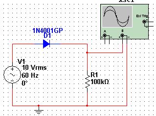
The basic circuit of the half wave rectifier is shown below:
The simulation of this circuit has been done using the NI multisim software.
Here we are using a 10V, 60Hz AC voltage source, 100K ohm resistor and pn junction diode 1N4001 all connected in series with each other. To check the waveforms of the load resistor R1, I have connected an oscilloscope across the resistor.
When the simulation starts, during the positive half cycle of the AC source, the diode is forward biased and hence act as a conductor, allowing the positive part of the since wave to pass through. During negative half cycle, the diode is reverse biased and hence act as an insulator, so the negative part of the wave appears as zero at the output.
Hence the sinusoidal wave is rectified partially. Since it is partially rectified, so it is called Half wave rectifier.
The output wave across the resistor R1 is shown in the snapshot shown below.
If you have any queries or any problem simulating this simple circuit then you can comment below.
Also read: Full Wave bridge rectifiers using diodes
One such simple and small rectifier is a half wave rectifier which uses a PN junction diode. Though this is not any advanced circuit which can be used for high accuracy rectification with minimum ripple, but still this circuit forms the basis of rectifiers.
In this post I am going to tell about the half wave rectifier circuit using PN junction diode.
The basic circuit of the half wave rectifier is shown below:
 |
| circuit simulation using NI Multisim - Click to enlarge |
The simulation of this circuit has been done using the NI multisim software.
Here we are using a 10V, 60Hz AC voltage source, 100K ohm resistor and pn junction diode 1N4001 all connected in series with each other. To check the waveforms of the load resistor R1, I have connected an oscilloscope across the resistor.
When the simulation starts, during the positive half cycle of the AC source, the diode is forward biased and hence act as a conductor, allowing the positive part of the since wave to pass through. During negative half cycle, the diode is reverse biased and hence act as an insulator, so the negative part of the wave appears as zero at the output.
Hence the sinusoidal wave is rectified partially. Since it is partially rectified, so it is called Half wave rectifier.
The output wave across the resistor R1 is shown in the snapshot shown below.
 |
| Rectified waveform across resistor R1 - Click to enlarge |
If you have any queries or any problem simulating this simple circuit then you can comment below.
Also read: Full Wave bridge rectifiers using diodes